Crash course in PV Hazard Control Systems at NABCEP 2024
This recap of a UL 3741 training session at NABCEP 2024 was originally published in the Q2 2024 edition of Solar Builder. The UL 3741 listing certifies equipment as a PV Hazard Control System, which is a pathway to comply with NEC 690.12, the code for rapid shutdown.
The concept of the PV Hazard Control System (PVHCS) was a much-needed code addition after NEC 2017 essentially forced installers to use module level electronics (MLE) to limit voltage within the array boundary to less than 80 V within 30 seconds. I hazard much-needed because …
- Solar installers should have more product and design choices, especially for large C&I rooftop projects.
- O&M reports the last several years show that dc connectors are a common failure point, and that improper connections are a safety hazard. So, code language that leads to an increased number of dc connectors via more MLE in the name of safety is counter intuitive.
- PVHCS is a step to codifying a more holistic view of the PV system — modules, connectors, racking, inverters, connectors, and wire management — and the risk it all poses to a first responder in a worst-case scenario.
In principle, designing a UL 3741 listed PV system can be simpler, because it largely relies on long-time PV design best practices, and less on an abundance of electronics (and dc connectors).
“I heard at the very beginning of UL 3741, some AHJs looked at it and thought they were just trying to cut corners,” says Justin Morgan, head of strategic sales for C&I with SMA America. “Well, no, because there’s all sorts of extra steps that go into it. … I think this goes back to a very similar way of installing systems that we used in the past, but with a lot of caveats, because there’s a lot of stuff we’ve checked on to ensure that you’re hitting all of the right safety protocols.”
In practice, at least right now, designing a fully compliant UL 3741 listed system can be confusing — especially on your first go-round.
I attended this UL 3741 training session, presented by SMA and Unirac, to clarify some questions and see what’s new in the market for adhering to this fledgling area of compliance.
PVHCS Definitions
PV Hazard Control System defined as “equipment coordinated to perform the function as described in the install manual to reduce the risk of electric shock within a damaged PV array for firefighters.”
A PV array is defined as “a mechanically and electrically integrated grouping of modules with support structure, including any attached system components such as inverter(s) or dc-to-dc converter(s) and attached associated wiring.
Enter the risk matrix
The NEC threshold of reducing the conductors’ voltage within the array boundary to less than 80 V was never fully substantiated based on actual risk to firefighters. On the other hand, with UL 3741, components are tested together to determine potential damage (via leakage current from the array) to a firefighter, wearing the appropriate PPE, in the worst-case scenario, such as falling into a damaged, wet PV module. The various tests are scored on a hazard matrix that includes probability of action and the hazard level from that action.
- What happens if the firefighter just accidentally kneels on a module?
- In scenario ABC, will voltage reduction be needed, or is voltage reduction unnecessary?
And so on. The worst-case scenario is figured to be a firefighter who is running and trips and falls and punctures a module with their axe. To simulate that, a sharp tool is dropped through a tube onto the module at a 3-ft height. The module is then taken off the racking and placed onto a test bed covered with a wet sheet, some foam and aluminum foil as a conductor. Then, a 1,000 V power source runs through the module to measure the leakage current that comes out. That leakage current is punched into the risk matrix (40 milliamps of exposure and below is considered the safe limit for a firefighter wearing wet PPE).
Based on the risk matrix testing, and in-depth installation addendum is provided.
“The crux of demonstrating that the hazard control system doesn’t exceed hazardous current levels comes down to wire management,” says Ryan Estrada, technical program outreach manager with Unirac. “If a firefighter falls on the module and there is current coming out, you want to ensure that there’s not a secondary fault path for that firefighter to become part of the current path. And that is accomplished through wire management.”
Expanded UL 3741 options
Commercially available equipment with the UL 3741 listing was not available until late 2021. The combined risk matrix score of the racking and wire management components determines how the system must be installed to actually comply with the UL 3741 listing.
For example, a metal rail-based racking system will score differently on the risk matrix than a non-conductive plastic bucket. So will a metal wire management clip vs. a plastic tie.
“Some will require voltage reduction in the array once rapid shutdown is initiated; so UL 3741 doesn’t preclude the use of any MLPE,” Morgan says.
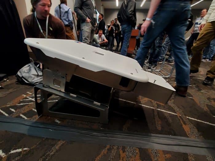
SMA was one of the first inverter manufacturers to earn the UL 3741 listing with its CORE1 inverter. A string inverter in a PVHCS must be situated within 1 ft of the array boundary, so the CORE1 has the advantage of being a free-standing unit that can fairly easily situate near that boundary.
That initial UL listing was in conjunction with Sollega racking, which is made of a non-conductive, UV-rated Nylon6 plastic. The bucket also extends out in such a way that it adds a few more crucial inches to the “array boundary.”
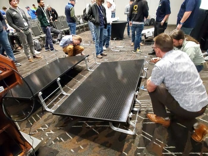
The UL 3741 listed marketplace has expanded exponentially since then, and this training session highlighted that by showcasing an array consisting of Unirac racking (made of metal) and SMA’s Sunny Tripower X, which needs to be mounted. The Sunny Tripower X and Unirac system has a UL 3741 listing up to 1,000 Vdc.
The big key to PVHCS design is wire management, and keeping live conductors away from metallic components. For Unirac, that is accomplished with non-metallic wire management. The demo example included a HellermannTyton module clip with a plastic loop that held the conductors. That air gap separation is key.
For row-to-row wire management to enclose the conductors, Unirac mentioned rigid PVC, as well as metal conduits, EMT metal tubing. “That threw me off at first too,” Estrada says, “but the argument here is, if you’re just doing row to row, those wires are fully protected inside your metal tubing, so there’s little chance of creating a secondary fault.”
Modern string inverters do not need to do anything extra special for a UL 3741 listing considering everything they already do. “You have to show that the inverter will be in rapid shutdown mode — it’s basically in anti-islanding mode,” Morgan says. “But other than that, there’s nothing new for us to do to meet UL 3741. This is really the one electrical designation that has nothing to do with us.”
Plus, the inverter must obviously still have AFCI and ground-fault detection systems as well as grid interactive features. Corner cutting, this is not.
PV Hazard Control System install addendums
Pay close attention to the installation addendum for UL 3741 systems. This is separate from the standard installation guide.
“There will always be an installation addendum for UL 3741 that has additional instructions,” Estrada says. “Those two documents have to be complied with. If you reference those with each system and judge against those, you should feel comfortable assessing that you have created a listed system.”
The Unirac addendum, for example, showed all of the inverters and wire management components listed for each of their five C&I racks. Unirac has a certified test lab in Boulder to do the testing, but then the testing is certified through an Nationally Recognized Testing Lab (NRTL). Each component must be tested with their system and resubmitted.
A common UL 3741 conundrum SMA has run into with the CORE1: A sub array with an isolated string that is attached well away from the others. Split compliance is one option (having that sub array installed with MLE to meet rapid shutdown and connecting that string to the CORE1), but it will trigger an alarm every morning. If that sounds annoying, you’d likely want to avoid it.
That’s why the 20 to 30 kW Sunny Tripower X UL listing is a “huge deal,” according to Morgan. “The Tripower X we thought would be used every once in a while on smaller systems, but some of the bigger companies I work with that are getting away from MLPEs, instead of doing split deployment, they’ll go with a couple 20 kW or 30 kW Tripower X’s depending on the array size. This supplements the CORE1 a lot. And there are still fewer connectors and less wire.”
The Tripower X mount is supplied by SMA to ensure UL 3741 compliance vs. introducing a component that would need to possibly be listed separately.
Scattered thoughts
- Key to the UL 3741 compliance of a metal racking system is plastic wire management. I found that curious considering the movement away from zip ties in PV systems the last few years. Maybe nothing wrong with this, but it did make me think the next step for solar PV code making is more consideration of longer term O&M implications.
- So, could an inverter be “mechanically attached” to a rail that extends out from the array, and then be considered part of the array? No one I spoke to could firmly say yes, but reading that language, it seems a reasonable conclusion. As always, it doesn’t matter what I, or you, or the manufacturers think. “A lot of times it’s up to the AHJs and their discretion,” Henning says. But I’m curious how creative system designers could be, considering that “mechanically and electrically attached” wording, when trying to connect awkward sub arrays.
- The industry could definitely benefit from design software that is coded with UL 3741 design principles.
Bottom line on PVHCS design
Whether you like Unirac or Sollega or PanelClaw for racking or SMA or SolarEdge or CPS for inverters, the bottom line of UL 3741 is solar installers and system designers have options again, all of which has been tested specifically for first responder safety.
UL 3741 has its kinks, but it makes more sense, to me, in achieving the goal of designing the safest PV systems for first responders while also reducing a PV system’s points of failure.
“We’re not saying these are safer than MLPEs; we’re just saying there are other benefits of designing a system like this,” Morgan says. “Ultimately this is just about complying with code and the true intent of it.”
I also like that UL 3741 is requiring all of these disparate manufacturers to come together to ensure the whole “PV system” that installers are cobbling together on rooftops will be compatible as a unified whole — tested to an objective safety standard.
I think Mike Mahon, Solar Academy manager with SMA America, summed it up best:
“My personal opinion is that poor workmanship can defeat any technology, so a standard that focuses more on workmanship and wire management should benefit everyone. Rapid shutdown is likely never going away, so improvement of the choices and working towards analysis-based methods to make sure that first responders are safe when interacting with a possibly damaged PV array is the best way forward.”
Chris Crowell is the Editor-in-Chief of Solar Builder.

Comments are closed here.