How mounting systems adapt to large format module stress
Large-format photovoltaic (PV) modules, also known as LFM, are made with larger cells than traditional modules, and are typically more than 2 meters long. Theses large-format modules have caused significant issues for traditional mounting and clamping strategies, forcing racking manufacturers to adjust.
“In the C&I sector, large format modules are now the norm and most rooftop PV designs,” notes John de Papp with PanelClaw.
As module sizes increase, existing engineering documents, which are based on smaller module dimensions, often become obsolete.
“Existing documents fail to account for the increased mechanical stresses and different load distributions introduced by the larger modules, necessitating a complete overhaul of mounting guidelines and practices,” says By Peter Abou Chacra with SunModo. “In regions with high wind loads, traditional module clamps used in racking systems become critical points of failure. The larger surface area of large format modules exerts greater force on each module clamp, which makes the clamps the weakest link in the system.
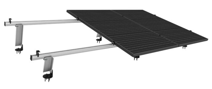
“This situation often forces installers to incorporate a third rail to better distribute the load and enhance the overall stability of the installation. Without such modifications, the risk of module clamp failure under high wind conditions increases, potentially leading to module damage or even system collapse.”
“These modules typically require long side clamping to handle the environmental loads (wind and snow),” de Papp said. “Shared, short-side clamping racking systems are simply not viable with these modules in most regions across the U.S.”
“Be sure to consider the total costed BOM, rather than just the panel cost, to ensure using larger panels saves money,” says Kai Stephan, CEO and Founder of Pegasus Solar.
Bessel points
As solar modules continue to grow in size and surface area, they face increased wind uplift pressure, which can create limitations on the allowable design pressure when clamping in certain areas, particularly near the corners of the modules.
“Traditional ballasted commercial mounting systems often use corner clamping, which can exacerbate these issues,” says Ryan Estrada, Technical Program Outreach Manager, Unirac. They adapted to these challenges by leveraging a principle known as Bessel points, named after mathematician and physicist Friedrich Wilhelm Bessel.
“This principle helps minimize the bending of horizontal beams by supporting them at specific, optimal locations. The result is that clamp locations consistently fall within the module’s allowable zones, often referred to as ‘quarter points.’ By avoiding corner clamping and instead using the more robust quarter point locations, we ensure a more reliable and durable system.”
Rail waste
Additionally, the higher module width of larger panels creates cut length issues and results in additional rail waste.
“Traditional rail lengths are optimized for smaller modules, leading to inefficiencies and increased material costs when adapted for larger panels,” Abou Chacra says. “This mismatch not only drives up installation costs but also contributes to environmental waste due to the excess rail material that cannot be utilized effectively.”
Emerging solutions
Emerging best practices and new product solutions are addressing these challenges.
“At SunModo, we are continuing to develop modular mounting systems that can easily scale to accommodate larger modules, while adjustable module clamps offer greater flexibility in mounting configurations. Furthermore, SunModo is expanding and improving its engineering documents to cover a wider range of module sizes, making our racking systems more scalable and modular.”
“With larger modules, we use a mid bucket to support the module,” notes Elie Rothschild, Sollega. “This ensures we can accommodate higher snow loads and comply with the module manufacturers clamping requirements.”
K2 Systems has the Cross Clamp that features a head that currently stands at 50mm wide, accommodating the largest sizes commonly called out by module manufacturers, notes Dakota Dominguez with K2 Systems. “Should larger panel sizes emerge in the future, we can simply switch out the head piece without creating a new part number.”
“Using the Pegasus Design Tool will enable quickly calculated total BOM costs to determine potential saves or costs from various panel sizes and the resulting changes to mount spans,” says Stephan with Pegasus Solar.


Comments are closed here.