Enhancing the safety of ground-mount and carport solar installations with MLPE
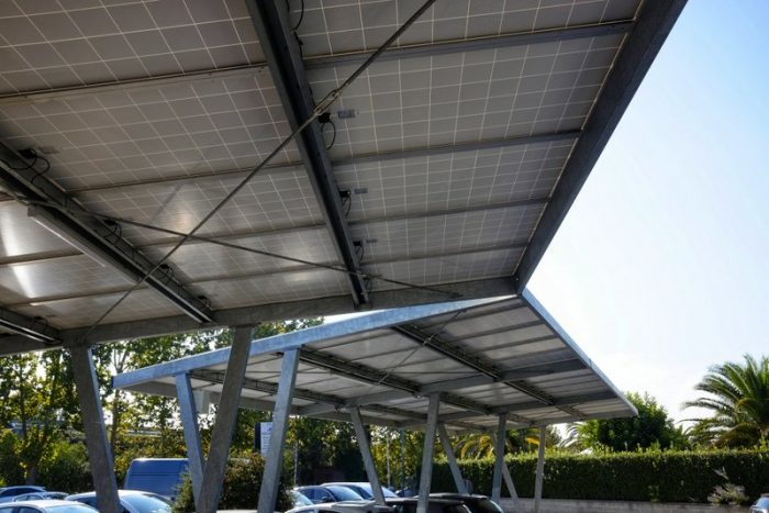
Rooftop solar safety has changed rapidly in recent years fueled by a combination of regulation and innovation. Here, Bill Brooks, NEC Expert and Principal, Brooks Engineering, and Kleber Facchini, Director of Commercial Product Management, and Jason Bobruk, Director of Code Compliance, both of SolarEdge Technologies, explain why the time is right to apply the same safety standards to carport and ground mount installations.
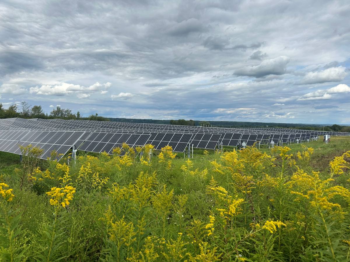
The past decade has been a transformative one for the solar industry. Demand has increased exponentially, driven in equal measure by the desire to act more responsibly and sustainably, and due to the economic advantages, made possible with years of technological advancements, that it can achieve. This proliferation is happening in the form of rooftop, carport, and ground-mount applications, all of which are needed to support the rapidly increasing demand for clean, renewable energy to power our world.
During this time, NEC regulations have advanced to include a minimum set of standards that must be implemented in rooftop PV systems to ensure the safety of both people and property. However, it is notable that – to date – no such regulations have been introduced for carport and ground-mount solar installations.
In part, this stems from the perception that, in the extremely unlikely event of a malfunction, rooftop PV poses more of a safety risk to people because it is physically closer to them. However, it can be argued that the same safety concerns are also present in carport and ground-mount applications.
For example, carports are inherently designed to shelter drivers as well as their vehicles. At the same time, the proliferation of ground mount installations will invariably bring these sites much closer to the homes and businesses they serve, and, as a consequence, to the people that live and work in them.
Without regulations to guide them, solar system owners and developers are left to weigh up the advantages of paying more for a PV system with enhanced safety features compared to the perceived level of risk. Yet the reality is that, if implemented, advanced safety solutions can not only help to mitigate risk, but they can also potentially save solar system owners millions of dollars in the long run.
Ground-fault scenarios in ground-mounts
It is important to note that fires where PV systems are installed are incredibly rare and generally do not originate from the PV system itself; electrical malfunctions or poor installation methods can be more common culprits. Regardless, it is essential to ensure that should a problem occur, the right equipment is in place to mitigate risks to both people and property.
For example, let’s consider what can happen in a solar installation if a ground-fault occurs – something that becomes more common as solar systems age.
While traditional central and string inverters are designed to recognize ground faults and will shut down the system until remedial action is taken, it is not uncommon for ground faults to be ignored, especially if the fault is perceived to be a nuisance issue, caused by moisture. Inverters are equipped to test for resistance isolation in the morning and will not start until the isolation resistance rises above a set threshold.
However, if the ground fault develops when moisture is present, the inverter may start later in the day, and it will not start at all if the ground fault is a persistent one. In both situations, while the ground fault is present and therefore a live connection to ground is present, array voltage relative to ground is kept at up to 1500 Vdc, opening the door for an immense risk to people and property, should a second fault occur.
When just one ground fault is present and the inverter is shut down, current is prevented from flowing through the ground path. However, if a second ground fault happens within the array, a second path to ground is created and undesirable, and in certain occasions unrestrained, circulating currents can occur.
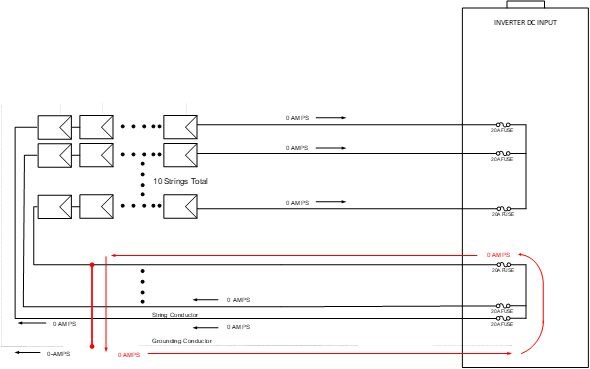
For example, Fig. 1 shows an ungrounded array with a ground fault that has developed between the negative wire of a string and ground. If the fault happens during inverter operation, the inverter will immediately shut off, ceasing ground current. However, even though the inverter is turned off, voltage levels up to 1500 Vdc will be present in the array while an active path to ground is present.
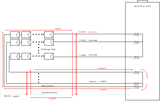
Fig. 2 shows the point where the second fault happens in an un-faulted string (i.e., a different string to the site of the first fault). This causes unrestrained current to flow until the combiner fuse clears, which can be a long time as fuse ratings are much higher than normal currents, which are also limited sources.
However, another, potentially much more dangerous situation can occur if the second ground fault develops in the same faulted string, as shown in Fig. 3.
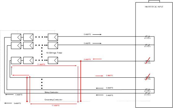
In this scenario, unrestrained current will keep flowing until sundown or until one of the paths to ground clears. This can cause an arc to develop, causing wire insulation to melt and resulting in hot debris being dropped onto anything beneath the array. This is highly undesirable in any situation. However, it poses even greater risks if the array is on a carport, due to the increasing presence of electric vehicles (with batteries) and high-power charging equipment that are housed underneath these structures.
Second, ground fault occurrences are likely to happen due to the fact that when a ground-fault occurs, the opposite pole is pushed to full PV open-circuit voltage. When this occurs, it makes it even more likely for damage to conductors and equipment on the opposite pole to fail (see Figs. 2 and 3). Industry experience with field failures has shown that once a ground fault is detected by a system, the second ground-fault is not far behind. A period of two weeks has been observed as a typical time period for a second failure. This has informed asset management procedures to recommend response time for a detected ground fault to be no longer than seven days from the initial event. This response time does not guarantee safety. It simply reduces the likelihood of a catastrophic failure.
Advancing safety with MLPE
The good news is that, with the development of module-level power electronics (MLPE) inverter technology, these potentially dangerous situations can be minimized – or even avoided altogether.
Advanced MLPE systems include built-in rapid shutdown functionality which automatically reduces voltage to the array to a safe level within ~30 seconds of a ground fault occurring, leaving secondary
ground faults virtually powerless to cause damage. This is due to the fact that once a ground fault is detected, the voltage level of the array will remain at safe levels as long as the path to ground is active.
Another important advantage of MPLE inverter technology is the ability to prevent arc faults from occurring.
Arc faults can occur between cabling and module connectors for a variety of reasons, including
unmanaged ground faults, aging, weathering, mechanical damage, physical damage by rodents, and improper installation. The resulting damaged joints decrease the cross-section area, effectively increasing the connection resistance and significantly increasing heat, which, if left unchecked, could turn into an arc fault in the future.
Advanced MLPE solutions mitigate this problem by constantly monitoring PV connectors for any increases in temperature. Should temperatures rise above a certain threshold, an event is triggered, and the voltage to the array is automatically reduced using the built-in rapid shutdown function, stopping the arc before it can occur. In a system without this capability, the only way to detect poor connections is at ground-level with a thermal camera. However, this is extremely labor intensive and cannot be carried out in real-time.
Risk-averse PV system owners who understand the safety concerns around carport and ground mount applications are now applying the same safety measures that have already been adopted in rooftop PV systems. In addition to the safety benefits outlined here, the use of MLPE also provides other key benefits. These include:
- BoS (balance of system) savings in installation and electrical equipment because of design flexibility and longer array strings;
- Increased energy production as energy is harvested at the module level with Maximum Power Point Tracking (MPPT); and
- Operations and maintenance savings with continuous, granular monitoring data and higher system uptime.
In conclusion, solar systems are now viewed as long-term investments that need to be managed and closely monitored to maximize the financial return. As with any significant investment, it is important to understand the impact of every decision, from design and component selection, choice of installer, and the operation and maintenance plan, because each impacts the safety, longevity, and return on investment (ROI) of the system.

Comments are closed here.