Install pros discuss wire management for rail-less solar on low-slope metal roofing
Rooftop rail-less solar PV systems have been around for many years, and year-over-year, continue to be a growing part of the solar market. Yet hesitancies still exist with both the technology and with learning new methodologies. One of these hesitancies is wire management.
We recently sat down with Doug Claxton, owner of The Solar Revolution and consultant with TSR Energy based in Boulder, Colo.; Mark Gies, solar expert and director of solar business with S-5!; and Shawn Haddock, senior field applications specialist with S-5!, to discuss wire management on low-slope rail-less PV systems.
Module preparation
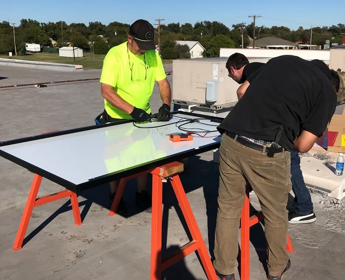
Prepping modules is one of the highly critical steps that must be planned, designed and executed to minimize installation time on the roof.
“Every project is unique, and there are many different methods for wire management and different combinations of products when it comes to home runs — but it can always be figured out before you get on the roof. That’s what I’ve seen helps installers the most” Haddock says. “I have shown up at jobsites, looked at their wire management design and thought, ‘this is crazy’. Then, we end up back at the office and spend the day working with the designers to come up with a better diagram that will now make the project days go faster.”
“On site, we typically have one or two people on the ground with a string diagram so they know how to properly prep the leads,” Claxton adds. “One of the first things we do is figure out how we are going to manage all the optimizer conductors because that is a challenge, but that challenge exists whether you have rail or not.”
Strategic string design
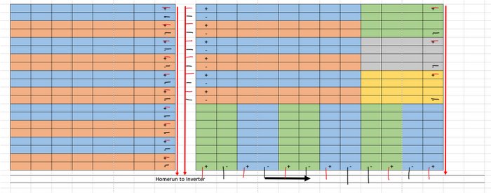
Take the time to strategically design your string layouts. This will enable you to minimize wire length, reduce the time it takes to clip up wires and plug in jumpers and also provide easy access to string ends, optimizers or microinverters. A few hours at the desk optimizing string design can save many hours or even days on the roof.
“On the front end, the system designer can make or break the job for installers on the roof, as well as for future O&M activities,” Claxton says. “We have always been big on cleaning up designs through logical string layouts and grouping home runs. I have seen layouts that tee up the installers for failure and make troubleshooting and diagnostics more difficult. I understand that sometimes the goal is to get as many Watts on the roof as possible, but I think you eventually pay the price for doing that as opposed to getting really clean layouts.”
Benefits of direct attaching solar modules to metal roofs
- Far fewer parts
- Huge reduction in freight cost
- Labor reduction
- Reduced handling/logistics
- Reduced dead load to the roof
- 25 percent better load distribution
- Speed of system installation
- Better wind resistance
Correction gaps
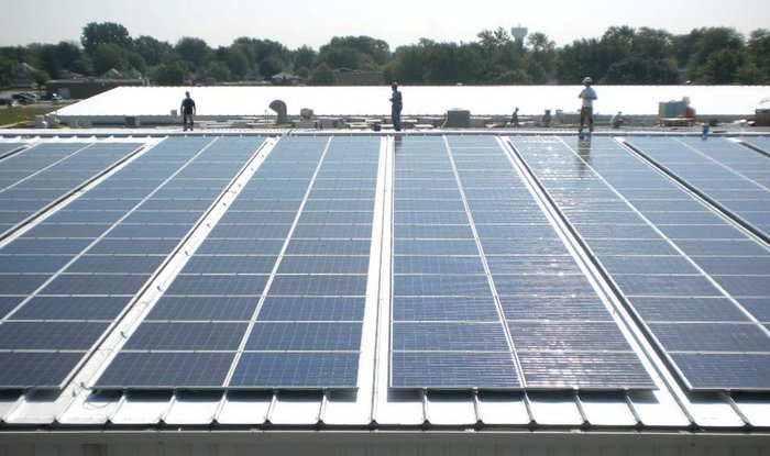
Although sometimes correction gaps are necessary (between pairs of modules) to align with metal roof seams, there is a clear benefit to creating a narrow walk space (shown above), which provides speeds access during installation and makes future O&M much easier and safer. The net loss of module space is usually below 3 percent (often it is zero).
“With correction gaps, you have easy access to every module on that project without having to walk on modules or worry about damaging them,” Haddock says. “You can quickly pull up a module, fix connections, and/or replace them. These gaps are essentially buffered spaces that allow for modules to be tweaked, improving the alignment and squareness of the array vs. the squareness of the roof. The gap can be as little as 1 in. or as large as 8 or 10 in., in which case it can be used as a walk space. Correction gaps can make the solar array more aesthetically pleasing from the ground.”
“This style works especially well when you have rooftops that have two-foot on-center seam spacing, which is common on low-slope commercial roofs,” Claxton says. “The gap provides the ability to walk between those twin module columns and not on top of the modules. This also facilitates wire management and MLPE replacement. In my opinion, the correction gap is well worth the small reduction in system size.”
Gies has worked with solar companies that design arrays with the number of rows or columns equaling the string sizes. “That is the ultimate design since all connectors, optimizers and microinverters are easily accessible from the array’s edge,” he says.
Trunk and branch wire management
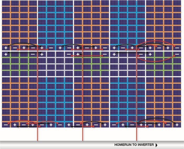
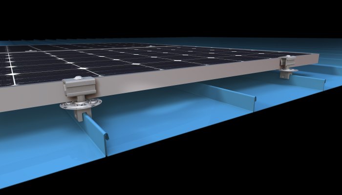
As sub-arrays get bigger and bigger, even with careful string and layout design, string ends may be located deep inside the module array. Wire trays can be installed underneath the modules to save significant time that would otherwise be needed to tie or clip up jumper wires on a direct path from the string ends to the home run (shown above).
“Wire jumpers can be routed to the wire tray, bundled inside it without any need for clips and then routed directly to the home run,” Gies says. “This method can also keep wires better organized.”
“When you are truly getting large, this would be a way to go,” Claxton adds. “But, a lot of times with a 100-kW system, with careful planning, you probably don’t need this. And, even with more than 100 kW, you are probably doing multiples of 100-kW blocks. This is certainly a good method if you have no choice but to bring a lot of jumpers to home runs or back to one central point.”
MLPE considerations
Both types of MLPE, optimizers and microinverters, have continued to gain traction in the solar market and are now more commonplace in rooftop projects of all sizes. MLPE can usually be installed by mounting to the module frame (shown on right) or directly to the roof. For some, there are specific reasons to mount to the roof, such as manufacturer requirements, but in most cases, mounting to the module frame is easier and most economical.
“I have heard various cases for both, but I am a big proponent of mounting MLPE right onto the modules,” Claxton says. “It allows for clean wire management that can be prepped in advance, making it easy for the installers who are setting the mods.
“Now, microinverters are another story, but I still think they are great to mount directly onto the modules,” he continues. “You can put a microinverter onto the module creating something similar to a true AC module. Then, it is a matter of managing the trunk cable, which can be accomplished with several wire management products intended for this purpose. From there, it’s just plug and go.”
Some installers may prefer to mount microinverters to the roof. Since a microinverter’s AC branch circuit is a single-trunk cable, both the microinverter and trunk cable cannot be installed together during the module prepping process. Others may prefer to mount microinverters to the metal roof using clamps and connecting them all to the AC trunk. This way, the modules are plugged in as they are set in place.
Additionally, other logistics such as the weight or size of the MLPE, or even local codes, may hinder or prevent direct attachment to the modules.
Tying it together
Strategically designing module and string layouts, prepping modules in staging areas and performing repeatable installation procedures overcomes all hurdles to installing rail-less solar. Even first-time installers of S-5’s new rail-less system have reported time savings of up to 50 percent.
Claxton concludes: “Start with the design; know all of the products at your disposal to achieve good wire management; use all of the products to mock it up; make sure that your configuration is actually what is going to work with the module, and then execute it with robotic repetition.”


Comments are closed here.