The value of engineering: How to optimize solar designs at every phase of a project
While “project optimization” and “value engineering” are typically thought of as something that occurs as a single effort during the phase when a project is about 30 percent designed, it is actually a continuous process that begins much earlier, and stretches much further, than that brief 30 percent design point.
Optimization and value engineering should be viewed as part of a holistic mindset that is always focused on decreasing costs and increasing value. As the 19th century American civil engineer Arthur Mellen Wellington once said, “an engineer can do for a dollar what any fool can do for two.” It is this mindset that can and should pervade each aspect of a solar project — from start to finish — to ensure each project is as valuable and cost effective as possible.
We have listed here the primary ways developers and engineering, procurement and construction companies (EPCs) can optimize solar projects through value engineering during several key phases using examples from recent projects in upstate New York.
Phase 1: Reduce excess equipment during utility interconnect application
One of the main ways to reduce costs when creating the designs for a utility interconnect application is to reduce excess equipment. As context, the majority of solar project designs start by copying a previous project so that the site layout drawings and single line diagrams can be quickly generated to make the utility interconnect application and get the project into the approval queue in the most cost-effective manner. During this phase, developers often don’t stop to contemplate why some equipment may or may not be included in the initial designs because they are focused primarily on proceeding with the interconnect application as quickly as possible. The person who completed the designs for the previous project, which the current project designs are based off of, might not have known why specific equipment was or was not included either, but they moved forward with the designs because they were approved and within budget.
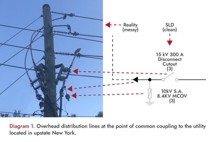
For example, for ground-mount projects with overhead distribution lines at the point of common coupling to the utility, we have been seeing various excesses in equipment, such as:
- Sets of surge arresters on every pole
- Extra disconnect switches
- Duplicate metering
Oftentimes, when there is a pole-mounted Gang-Operated Air Break (GOAB) switch located two poles down from a hot-stick (live line tool) operated disconnect switch, it is unlikely that anyone will ever use the hot-stick operated switch since they can just open and lock at the GOAB from the ground.
Beyond that fact that the live line tools in these situations are excessive and add unnecessary additional costs, live line tools are also unwieldy because of their length, difficulty to use and are subject to OSHA-required testing every two years, which results in further avoidable costs.
Although some of these excessive devices are not big ticket items, if they are functionally redundant or won’t be used whatsoever, then there is no reason to spend money on them that could otherwise be saved or invested in other aspects of the project. Always strive to minimize the bill of materials (BOM) to complete the job in the most cost-effective manner possible.
Phase 2: Eliminate redundancies during equipment procurement
Another key method for reducing costs on a solar project is to thoroughly review and eliminate any redundancies during the equipment procurement phase.
For example, in a suite of five different 5-MW projects in upstate New York for a client of ours, we were engaged to execute the engineering after the interconnect approval was received. Our client’s first task for us was to comment on the balance of plant equipment quotes that they had received. The items that were reviewed included:
- 15-kV recloser
- Grounding transformer
- Combiner boxes
- Pole-mounted metering cluster
- Pole-mounted GOAB switch
- Pole-mounted fuse cutouts
- Data acquisition system
- Aux power transformer and panel
- Surge arresters
- Secondary metering
After conducting a thorough review and analysis, we were able to identify hardware savings of over $200,000 for each of the five projects. The majority of these savings were derived through the elimination of redundant equipment and the reduction of overspecifications on other equipment.
Phase 3: Mitigate cable cost, considering future O&M costs, during design
A crucial aspect of the design phase is being able to work with the contractor early on to determine equipment preferences, as this can significantly reduce future operations and maintenance (O&M) costs.
For example, deciphering the maximum desired size of cable to be run is key, such as 800-kcmil maximum single aluminum conductor and 600-kcmil maximum dual aluminum conductors. Other typical questions that influence the design, and thereby the project costs, are:
- The preferred locations of the combiner boxes
- Whether the combiner boxes will be provided with pre-installed Unistrut mounting rails
- What the desired vehicle access widths and turn-around areas are.
Examining the trade-offs in combiner box locations is a multi-variable effort because ease of access for O&M work might come at the expense of either longer string conductors or combiner box output conductors. Also, if trenching is being utilized, that cost needs to be factored in as well.
With the price of materials drastically increasing over the last year, we have seen some clients start to consider loosening their voltage drop criteria because the reduced losses from larger cables now have a significantly longer payback, while others are maintaining their strict voltage drop criteria. Typical criteria will be to target a 1.5 percent average dc voltage drop, with a worst case allowable dc voltage drop of 2 percent, which can be a real challenge for uniquely shaped solar sites.
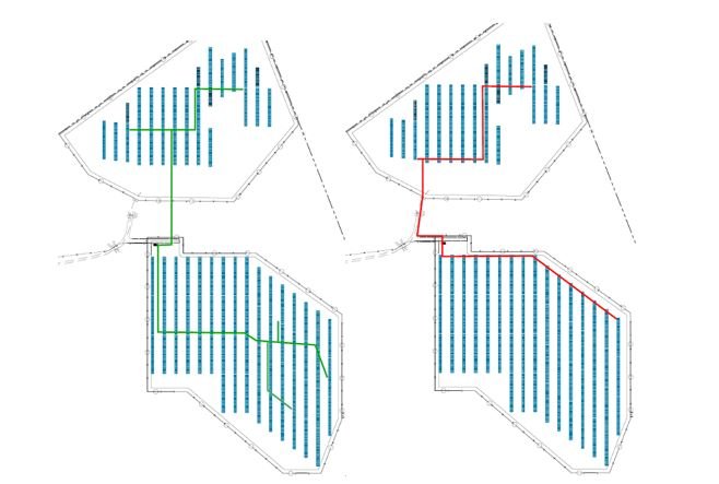
Diagram 2 is an example from one of our recent projects in upstate New York. It shows combiner box locations and trenching as originally designed to optimize cable lengths, sizes and voltage drop in green, and contractor recommended locations to minimize trenching in red.
While the contractor recommendations minimize trenching and the length of aluminum combiner box output conductors and conduit, the table below indicates the drastic increase in length for the copper string wiring, along with an increase in average dc voltage drop from 1.5 percent to 1.7 percent.
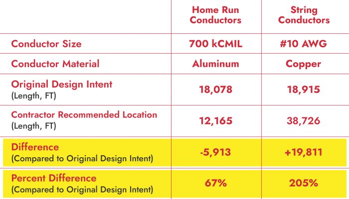
The final design that Castillo Engineering produced required several iterations in order to find the optimal compromise between the original design and the contractor recommended design.
A multitude of factors must be considered when designing a solar project, including future O&M costs. Recommendations for equipment, such as conductors, can vary greatly. It is pertinent to perform a thorough analysis to determine the pros and cons of each design in order to find the optimal solution.
Phase 4: Reduce time, costs with flexibility during extended post-design
Developer and EPC clients sometimes can bring solar projects to design and engineering firms that have challenging design schedules. In these situations, Phases 1 through 3 are combined and often lead to fourth phase — extended post-design. Adaptability in these situations is paramount to keep costs down and meet tight deadlines.
For example, we recently received a 6.6-MW solar tracker project in New York that used string inverters and had a challenging design schedule. The client submitted the basic project information to us on a Tuesday and requested that we generate a 60 percent design in accordance with their standards in one week.
Our standard contract schedule is four weeks to produce a 90 percent submittal, so a significant amount of design work was compressed, and it was hampered by not having a CAD file for a layout drawing or any racking information. This is not the first time that we have proceeded based on PDFs, and we were able to utilize the appropriate racking details from our project library to submit the 60 percent set in one week, as requested.
There were then multiple iterations of the 90 percent design, as we received various sets of client and owner comments in addition to a racking layout change and various changes in PV module selections due to availability and cost. Some comments were small in scale, such as the removal of two strings on a half table, which was later changed to the original design intent, returning the two removed strings back into the array. Most of these design iterations were requested with a one-day turnaround time, two days maximum. Issue for construction (IFC) drawings were finally issued to meet the schedule with some equipment still “on hold” from the lack of receiving shop drawings. However, despite these significant challenges, this project is being successfully executed with a minimum amount of contractor requests for information (RFIs).
Bottom line
At Castillo Engineering, we have learned over 25 years (and over 300 utility-scale solar projects), that it is a rare project indeed that proceeds from the 30 percent initial design to the 60 percent design to the 90 percent design (issue for permit) and then to the 100 percent design (issue for construction) with only one set of comments to incorporate at each stage. The recent supply chain issues have also created a large increase in material substitutions being requested well into the construction phase simply due to lack of availability of the preferred equipment.
At the end of the day, being able to recognize and implement opportunities for optimization at almost any stage of the project through major mechanical completion, paired with a high level of flexibility, are key to mitigating costs and maximizing project value.
Joe Jancauskas is a senior electrical engineer at Castillo Engineering, bringing 30 years of engineering experience, primarily working for utilities and solar EPCs. Joe holds a bachelor’s degree in electrical engineering and a master’s in engineering management. John Cruz is a solar engineer at Castillo Engineering. He has a bachelor’s degree in electrical engineering from the New Jersey Institute of Technology.


Comments are closed here.