Definitive Guide to UL 3741: Every pathway for NEC compliance
By Ryan Mayfield, founder and SME at Mayfield Renewables. This article was originally published in the Q1 2025 issue of Solar Builder magazine.
Over four years after its release, UL 3741, Standard for Photovoltaic Hazard Control, still has the PV industry abuzz. Go to any conference floor and simply utter the words. Like it or not, you’ll find someone willing to share their opinions on the topic and elaborate on why yours are wrong. The UL 3741 standard is a topic Mayfield Renewables tackled early and often as we have worked with our clients and manufacturers to provide UL 3741-compliant designs.
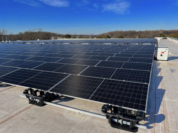
The solar industry has seen several racking manufacturers release systems that meet the UL 3741 standard. The first systems released were limited to low-slope commercial applications. Within the last year, multiple manufacturers released pitched roof solutions utilizing 3741. In addition, some MLPE manufacturers have listed their products to UL3741, allowing multiple modules in a series string.
After four years, you’d think the dust would have settled, and the topic would be old news. However, the standard is still misunderstood within the industry and by Code officials charged with verifying the proper installation practices. I’ll explore the industry’s current state, and the typical applications designers, installers, and inspectors encounter.
UL3741 and the NEC
Before applying UL 3741 in PV installations, let’s take a step back and look at the 2023 National Electrical Code (NEC) requirements driving us to the standard. Section 690.12, Rapid Shutdown of PV Systems on Buildings, is familiar to most PV professionals. Regarding the UL 3741 standard, our focus is subsection 690.12(B)(2), where the charge is controlling the conductors, explicitly controlling the shock hazard, within the array boundary. Two additional subsections provide us with paths to meet this requirement.
Installing MLPEs on all rooftop arrays has been the most common solution to meet 690.12(B)(2). This installation method is the most straightforward way to limit the voltage of the conductors within the array boundary to less than 80 V within 30 seconds of rapid shutdown initiation per 690.12(B)(2)(2).
The 80 V threshold was admittedly a value chosen without any empirical data to substantiate it. 80 V was a value the code-making panel could support because it was low enough to minimize any hazard yet high enough to allow then-current installation practices (through MLPE) to continue.
Using 80 V as the upper threshold effectively eliminated the ability to connect two or more PV modules in series and still meet the requirement. Therefore, until the release of UL 3741 systems, MLPEs were the only way to meet the Code requirements. Now, we see UL 3741 systems that allow for voltages within the array boundary from 80 V up to the allowable maximum value of 1,000V.
690.12(B)(2)(1) calls out the use of a PV hazard control system (PVHCS) to “provide shock hazard control for firefighters” as one method to meet the requirements to control the conductor limits within the array boundary.
“Provide shock hazard control for firefighters” is also added to the Code to help clarify the purpose of these systems and who they serve. UL 3741 provides an alternative to the previous sole solution of utilizing MLPEs on all rooftop PV arrays to meet the 690.12 requirements for conductors inside the array boundary. The informational note that follows 690.12(B)(2)(1) explicitly calls out UL 3741 and drives home the purpose of the PV hazard control systems.
UL 3741 Overview
The premise of UL 3741 was to define electrical hazards firefighters encounter when interacting with PV systems and then provide testing standards to mitigate those risks. UL formed a standards technical panel (STP) and engaged industry stakeholders, Sandia National Laboratories, and the US Department of Energy to gather data to define firefighters’ hazards when performing their duties near a rooftop PV system.
The STP developed numerous parameters to substantiate the shock hazards imposed on firefighters. These included the electrical resistance of standard, OSHA-required safety gear, the electrical body resistance of adult male and female firefighters, and the multiple failure modes that firefighters may encounter, exposing them to shock hazards.
This work defined shock hazards based on specific voltage, current, and resistance measurements. The result is a repeatable test method to ensure consistent and verifiable results. To pass the testing, manufacturers must prove that firefighters will not be exposed to shock hazards in various scenarios, including when firefighters fall on PV equipment with tools in their hands and on their belts.
This protection can take various forms, including switches, power electronics, inverter controls, and/or physical protection of conductors. The variability in the methods to provide the shock hazard makes it essential for designers and installers to understand the exact manufacturer requirements and follow the UL 3741 documentation to verify systems meet the standard.
Applying 3741 and the NEC
To apply the standard to the Code, we must first define the conductors subject to control.
Open the Digital Edition of Solar Builder magazine for the rest of the article and diagrams for each scenario.

Comments are closed here.